
KE2 Temp Controller Manual: A Comprehensive Guide
This document serves as a comprehensive resource for understanding and utilizing the KE2 Temp controller. It provides a detailed walkthrough of its features, operation, and troubleshooting, ensuring optimal performance and longevity.
KE2 Temp controllers are designed to simplify refrigeration controls, combining thermostat and defrost timeclock functions. These controllers are ideal for various applications, offering precise temperature management and energy savings. They are versatile and can be used in various refrigeration systems, enhancing overall efficiency. KE2 Temp controllers offer advanced features like air defrost, adaptive control, and low-temperature defrost evaporator efficiency. With their user-friendly design and comprehensive functionality, KE2 Temp controllers are a valuable asset for any refrigeration setup. This manual will guide you through the installation, operation, and troubleshooting of these innovative controllers, ensuring optimal performance and longevity of your refrigeration system.
Overview of KE2 Temp Controller Functionality
KE2 Temp controllers combine thermostat and defrost timeclock functions for simplified refrigeration control. The controllers manage refrigeration and defrost cycles via a single-pole-double-throw relay. They can display room temperature (rtp), superheat (SH), suction pressure (PrS), or leaving liquid temperature (LLT). Alternate modes can drive EEPR or EHGP valves for pressure or temperature control. The controllers offer features like manual defrost and visual alarming for operational convenience. Fan delay temperature settings allow for precise control after defrost cycles. KE2 Temp controllers enhance energy savings, provide precise temperature control, and reduce frost. These controllers are designed for easy installation and use, improving overall refrigeration system efficiency.
Thermostat and Air Defrost Control
The KE2 Temp controller integrates thermostat and air defrost functionalities to streamline refrigeration management. It effectively combines the roles of a thermostat and defrost timeclock, simplifying control mechanisms. The controller’s air defrost capabilities ensure efficient frost removal, optimizing evaporator performance. Manual defrost options are available, providing flexibility in maintenance. Visual alarms alert users to potential issues, enhancing system monitoring. The controller’s design simplifies refrigeration by integrating defrost cycles with temperature regulation. This integrated approach enhances energy savings and reduces frost buildup. The KE2 Temp controller offers precise thermostat and defrost management, ensuring efficient and reliable refrigeration system operation. The single-pole-double-throw relay manages refrigeration and defrost cycles.
EEV, EEPR, and EHGP Valve Control
The KE2 Temp controller offers versatile valve control capabilities, supporting EEV, EEPR, and EHGP valves. In alternate modes, it can drive EEPR or EHGP valves for pressure or temperature regulation. This adaptability enables precise control of refrigeration systems, catering to diverse operational needs. EEV control provides accurate superheat management, optimizing system efficiency. EEPR valve control allows for precise pressure regulation, enhancing system stability. EHGP valve control facilitates temperature management, ensuring consistent performance. The controller’s flexible valve control options enhance system performance and adaptability. It offers precise and responsive control over various valve types. The KE2 Temp controller ensures efficient and reliable refrigeration system operation through its adaptable valve control features. These features contribute to energy savings and optimal system performance, providing a comprehensive solution for refrigeration management.

Installation and Wiring
Proper installation and wiring are crucial for optimal KE2 Temp controller performance. This section provides detailed instructions and guidelines for connecting the controller and ensuring correct operation.
Wiring the Controller
When wiring the KE2 Temp controller, ensure the power supply is disconnected to prevent electrical shock. Identify the appropriate terminals for power input, sensor connections, and relay outputs based on the controller model and wiring diagram. Use appropriately sized wires and secure connections to prevent loose contacts.
The controller typically supports 120V or 208-240V input voltage. Consult the manual for specific voltage requirements. Connect the temperature sensor(s) to the designated terminals, paying attention to polarity if applicable. The single-pole-double-throw relay controls the refrigeration and defrost cycles. Refer to the wiring diagram for proper relay connections.
Double-check all wiring connections before applying power to the controller.
Removing the Display for Wiring
To access the wiring terminals of the KE2 Temp controller, it may be necessary to remove the display unit; Before doing so, ensure that the power to the controller is disconnected. Locate the four corner screws securing the display to the main unit. Carefully loosen these screws using an appropriate screwdriver.
Once the screws are loosened, gently detach the display from the lower board. Be mindful of the short ribbon cable connecting the display to the main board. Avoid pulling or straining the ribbon cable, as this could damage the connection. With the display removed, the wiring terminals will be accessible for making necessary connections.
Supplies List for Installation
When installing a KE2 Temp controller, having the correct supplies readily available will streamline the process. While the controller typically comes with essential accessories, certain truck stock items might be needed to complete the installation. A temperature sensor, often a 45-inch model, is generally included for accurate temperature readings.
Beyond the included items, consider having wire connectors, wire strippers, a screwdriver set, and a multimeter on hand. Depending on the specific installation environment, you may also require mounting hardware, conduit, and electrical tape. Consulting the specific installation instructions for your KE2 Temp controller model is highly recommended to ensure you have all necessary supplies.

Operation and Settings
This section details the operational aspects of the KE2 Temp controller, covering key settings such as manual defrost, fan delay temperature, and adjusting room temperature setpoints for optimal performance.
Manual Defrost Function
The KE2 Temp controller offers a manual defrost function, providing users with the ability to initiate a defrost cycle on demand. This feature proves invaluable in situations where frost buildup is excessive or when a scheduled defrost cycle is insufficient. To activate manual defrost, consult the controller’s interface and locate the designated button or menu option. Activation typically involves pressing and holding the button for a specified duration. The controller then initiates the defrost sequence, melting away accumulated frost. The manual defrost function is essential to maintain evaporator efficiency and optimize system performance. Understanding its operation is crucial for effective refrigeration management. This ensures that the system operates efficiently.
Setting the Fan Delay Temperature
The KE2 Temp controller incorporates a fan delay temperature setting, a critical parameter influencing fan operation after a defrost cycle. This setting determines the coil temperature threshold that must be reached before the fan resumes normal operation. To configure this setting, access the controller’s parameter menu and locate the fan delay temperature option. Input the desired temperature value, ensuring it is appropriate for the application and prevents ice formation. Setting an appropriate fan delay temperature prevents blowing warm air into the refrigerated space immediately after defrost. This helps maintain stable temperatures. This enhances energy efficiency. Correctly setting this parameter guarantees optimal temperature control, and protects the evaporator.
Adjusting Room Temperature Setpoints
The KE2 Temp controller allows precise adjustment of room temperature setpoints, ensuring optimal conditions within the refrigerated space. To modify these setpoints, navigate to the controller’s parameter menu and locate the room temperature setting. Input the desired temperature value, considering the specific requirements of the stored product. Ensure that the setpoint is within the controller’s operating range and aligns with industry standards. The controller utilizes these setpoints to maintain the desired temperature. It activates the refrigeration system as needed. Precise adjustment prevents temperature fluctuations and spoilage. Furthermore, confirm the secondary setpoint, which serves as a backup. Regular review and adjustment of setpoints are crucial. This helps maintain product quality. It optimizes energy consumption.
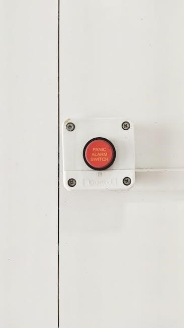
Understanding Visual Alarming
The KE2 Temp controller employs visual alarming to promptly alert users to potential issues within the refrigeration system. These alarms are displayed on the controller’s screen. They provide immediate indication of abnormal conditions. Common visual alarms include high temperature alerts, low temperature alarms (LtA), and defrost malfunction indicators. Each alarm corresponds to a specific problem, enabling quick identification and resolution. The visual alarm system helps to prevent product spoilage and equipment damage. Upon triggering an alarm, investigate the root cause promptly. Consult the KE2 Temp controller manual for detailed troubleshooting steps. Furthermore, some alarms may require manual acknowledgement or reset after the issue is resolved. This ensures proper system operation and prevents repeated alerts. Visual alarming is critical for maintaining system integrity.

Troubleshooting and Error Codes
This section provides guidance on resolving common issues with your KE2 controller. It includes troubleshooting steps and explanations of error codes. Consult this section for efficient problem diagnosis and resolution.
KE2 Controller Troubleshooting
If you encounter issues with your KE2 controller, begin by checking the power supply and ensuring all wiring connections are secure. Verify that the controller is receiving the correct voltage, typically 120V or 208-240V. Inspect the temperature sensors for damage or loose connections, as faulty sensors can cause inaccurate readings and operational problems.
Refer to the visual alarming system for clues, paying attention to high or low-temperature alerts. For refrigeration problems, confirm the thermostat settings and defrost cycles. If problems persist, consult the KE2 Temp controller codes for detailed error information and contact technical support if necessary.
KE2 Temp Controller Codes
The KE2 Temp controller utilizes a series of error codes to indicate specific issues and simplify troubleshooting. These codes are displayed visually on the controller’s interface, providing valuable insights into potential problems. Refer to the comprehensive list of codes in the manual to identify the root cause of any malfunction.
Common codes may relate to sensor failures, communication errors, or temperature deviations. Understanding these codes allows for targeted troubleshooting, reducing downtime and ensuring efficient operation of the refrigeration system. Always consult the detailed descriptions within the manual for the recommended corrective actions associated with each code.

Advanced Features
The KE2 Temp controllers offer advanced features like adaptive control, air defrost capabilities, and low temp defrost evaporator efficiency. These features optimize performance and energy savings in refrigeration systems.
Air Defrost Capabilities
The KE2 Temp controller’s air defrost capabilities simplify refrigeration controls by combining thermostat and defrost timeclock functions. This feature eliminates the need for external defrost timers, reducing complexity and potential failure points. Air defrost leverages ambient air to remove frost, offering an energy-efficient alternative to traditional methods.
The controller monitors coil temperature and initiates defrost cycles based on pre-set parameters or manual activation. This ensures efficient frost removal while minimizing temperature fluctuations within the refrigerated space. The air defrost function contributes to improved evaporator efficiency and overall system performance. It enhances product preservation, reduces energy consumption, and simplifies maintenance.
Adaptive Control Features
KE2 Temp controllers incorporate adaptive control features, optimizing performance based on real-time conditions. This allows for intelligent adjustments to refrigeration cycles, enhancing energy efficiency and product preservation. The controller continuously learns from environmental factors, such as temperature fluctuations and usage patterns, adapting its operation accordingly.
Adaptive control minimizes temperature swings, preventing product spoilage and maintaining consistent conditions within the refrigerated space. It also reduces energy consumption by optimizing compressor run times and defrost cycles. The controller’s ability to adapt to changing conditions ensures efficient and reliable operation, reducing maintenance costs and maximizing system lifespan. This advanced functionality promotes sustainable refrigeration practices.
Low Temp Defrost Evaporator Efficiency
KE2 Temp controllers prioritize evaporator efficiency during low-temperature defrost cycles. These cycles are crucial for removing frost buildup, which can significantly impede heat transfer and reduce refrigeration performance. The controller employs strategies to minimize energy consumption and maintain stable temperatures throughout the process, optimizing the defrost cycle duration based on frost accumulation.
By carefully managing defrost initiation and termination, the KE2 Temp controller prevents over-defrosting, conserving energy and minimizing temperature fluctuations. This approach ensures rapid recovery to optimal operating conditions after defrost, maximizing evaporator efficiency and overall system performance. Efficient defrosting also extends the lifespan of evaporator components by reducing stress and thermal shock.

Specific KE2 Controller Models
KE2 offers diverse controller models, each tailored for specific refrigeration applications. These include controllers optimized for air defrost, valve control, and evaporator OEM integration, ensuring application-specific functionality.

KE2 Temp Air Defrost Controller
The KE2 Temp Air Defrost controller simplifies refrigeration control by combining a thermostat and defrost timeclock. This controller is designed to manage refrigeration and defrost cycles using a single-pole-double-throw relay, and it uses air defrost. The KE2 Temp Air Defrost controller combines the functions of a thermostat and defrost timeclock, making it easier to manage refrigeration controls. Visual alarming is included, alongside manual defrost capabilities. The controller ensures energy savings, precise temperature control, and frost reduction, enhancing overall evaporator efficiency. It features adaptive control for optimized performance and offers comprehensive communication capabilities. This model is designed to simplify refrigeration control by combining the function of a thermostat and defrost timeclock.
KE2 Temp Valve Controller
The KE2 Temp Valve Controller is designed to manage pressure or temperature by driving an EEV, EEPR, or EHGP valve, offering versatile control options. This thermostat and air defrost controller can drive an EEV and provides a quick start guide and complete instructions for installation and use. Alternate modes allow it to drive an EEPR or EHGP valve. The KE2 Temp Valve Controller manual provides a comprehensive guide for its installation, operation, and troubleshooting. It is designed for precise temperature regulation and energy savings. The display shows room temperature (rtp), superheat (SH), suction pressure (PrS), or leaving liquid temperature (LLT) depending on control type and setup. The detailed user manual provides a quick start guide and complete instructions for the installation and use of the KE2 Temp Valve.
KE2 Evap OEM Controller
The KE2 Evap OEM Controller delivers energy savings, precise temperature regulation, frost reduction, and communication capabilities, similar to the KE2 Evaporator Efficiency system. This controller is designed for Original Equipment Manufacturers (OEMs) to integrate advanced control features into their refrigeration systems. The KE2 Evap OEM provides the energy savings, precise temperature control, frost reduction, and communications capability of the KE2 Evaporator Efficiency. Its compact design and flexible programming options make it ideal for a wide range of applications. It offers precise temperature control and helps reduce frost build-up, improving overall system efficiency. The controller’s advanced features contribute to significant energy savings, making it an environmentally friendly choice. It is also designed for ease of integration and use.

Alarms and Indicators
The KE2 Temp controllers use visual alarms to indicate system malfunctions or out-of-range conditions. These alarms help users quickly identify and address issues, ensuring efficient operation and preventing potential damage.
Low Temperature Alarm (LtA)
The Low Temperature Alarm (LtA) is a critical feature of the KE2 Temp controller, designed to alert users when the system temperature falls below a predefined threshold. This alarm is crucial for preventing damage to temperature-sensitive goods and ensuring optimal system performance. When the LtA is triggered, the controller will display a visual warning, prompting the user to investigate the cause of the temperature drop. Possible causes include malfunctioning components, inadequate insulation, or improper setpoints. Addressing the LtA promptly is essential for maintaining product integrity and preventing costly downtime. Consulting the KE2 Temp controller manual for specific troubleshooting steps is highly recommended.

Display Information
The KE2 Temp controller’s display provides real-time data, including room temperature, superheat, suction pressure, and leaving liquid temperature, depending on the model and configuration, aiding in system monitoring and adjustments.
Displaying Room Temperature (rtp)
The KE2 Temp controller displays the current room temperature (rtp), providing users with crucial information for maintaining desired conditions. This real-time reading allows for immediate assessment of the environment and necessary adjustments to the system. Monitoring the rtp ensures that the temperature remains within the set parameters, preventing potential issues related to overheating or undercooling. By observing the displayed rtp, users can promptly identify any deviations from the desired temperature range and take corrective actions. This feature is essential for optimizing energy efficiency and maintaining product integrity in various applications. Consistent monitoring of room temperature contributes to a stable and controlled environment, promoting overall system performance. Regular observation helps to ensure the temperature is within the specified range.
Displaying Superheat (SH)
The KE2 Temp controller’s ability to display superheat (SH) provides critical insights into the refrigeration system’s efficiency and performance. Superheat, the temperature of the refrigerant vapor above its saturation point, is a key indicator of proper refrigerant charge and evaporator operation. Monitoring SH allows technicians to optimize the system for maximum cooling capacity and energy efficiency. A correct superheat value ensures the compressor receives only vapor, preventing potential damage from liquid refrigerant. By observing the displayed SH value, users can identify issues such as refrigerant undercharge or overcharge, airflow problems, or evaporator malfunctions. Regular monitoring and adjustments based on the SH reading contribute to a more reliable and efficient refrigeration system. Optimal superheat can help extend the lifespan of the compressor and other components, thus providing significant cost savings over time. This precise monitoring is crucial for preventing inefficiencies.
Displaying Suction Pressure (PrS)
The KE2 Temp controller’s capability to display suction pressure (PrS) is vital for monitoring the low-pressure side of the refrigeration system. Suction pressure, measured at the compressor inlet, indicates the refrigerant’s saturation temperature within the evaporator. This parameter is crucial for diagnosing issues affecting the evaporator’s ability to absorb heat. A low suction pressure may suggest a refrigerant undercharge or a restriction in the liquid line, while a high suction pressure could indicate overcharge or poor airflow across the evaporator coil. By monitoring the PrS on the KE2 Temp controller, technicians can promptly identify and address imbalances, maintaining optimal system performance. Regular observation of suction pressure ensures the evaporator operates efficiently, promoting consistent cooling and preventing compressor damage. Properly maintained suction pressure contributes to energy savings and extends the lifespan of refrigeration components. Accurate readings are essential for proactive maintenance.
Displaying Leaving Liquid Temperature (LLT)
The KE2 Temp controller, depending on the control type and setup, can display the Leaving Liquid Temperature (LLT). LLT is measured as the refrigerant exits the condenser, providing critical insights into the subcooling process. A stable LLT indicates efficient heat rejection in the condenser, ensuring the refrigerant is adequately cooled before entering the expansion valve. Monitoring LLT helps diagnose condenser issues, such as fouling or insufficient airflow, which can lead to reduced system capacity. A high LLT can cause increased energy consumption and reduced cooling capacity. Conversely, a low LLT may suggest overcooling or issues with refrigerant flow. By displaying LLT, the KE2 Temp controller enables proactive monitoring, allowing technicians to optimize system performance and prevent potential problems. Regular observation of LLT helps maintain efficient operation, contributing to energy savings and prolonged equipment life. Accurate readings facilitate informed decisions.